Getting the most out of IGBTs is about knowing When, Where and How to Use Them
Nowadays, bandgap semiconductors like silicon carbide (SiC) and gallium nitride (GaN) steal most of the limelight; however, before these arrived on the scene, insulated gate bipolar transistors (IGBTs) were the power electronics workhorses. In this blog, we look at some applications where IGBTs continue to prove their worth before taking a quick look at what the future might hold for these versatile devices.
Welding Machines
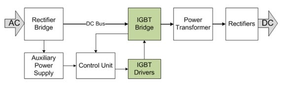
Many modern welding machines use an inverter instead of a welding transformer because a DC output current allows more accurate welding process control. Other advantages are that DC currents are safer than AC, and inverter-based welding machines are lighter due to higher power density.
Figure 1: Block diagram of welding machine
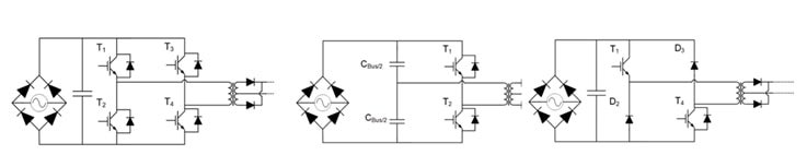
Common switching topologies in welding inverters include full-bridge, half-bridge, and double-switch forward, typically with a constant current control scheme. The IGBT switching frequency for full-bridge and half-bridge topologies is generally between 20 and 50 kHz.
Figure 2: IGBTs in Full- and Half-Bridge and Double-Switch Forward topologies for welding
Induction Cooking
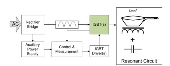
Induction stove cooking involves exciting a coil of wire which forces a current to circulate in a pot made of a material with high magnetic permeability. Next, an inverter induces current into the copper coil, which generates an electromagnetic field. This penetrates the pot and generates a current causing it to heat up.
Figure 3: Block diagram of an induction stove
The essential requirements for induction stoves include the following:
- High frequency switching
- Power factor close to one
- Wide load range
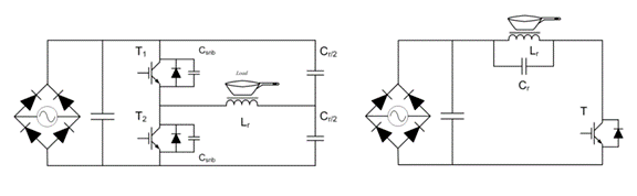
Topologies based on a resonant tank are the most commonly used because these have the advantage of being able to switch at high frequencies without compromising efficiency - the resonant half-bridge (RHB) converter and the quasi-resonant (QR) inverter are the most popular. The advantage of the RHB is that it has a high range of load operation and can deliver maximum power. On the other hand, QR is lower cost, making it ideal for low- to mid-power ranges (up to 2 kW peak power).
Figure 4: RHB and QR topologies
Motor Drives
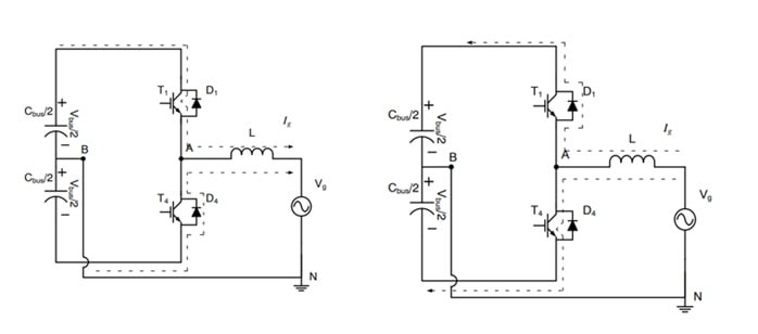
The half-bridge converter (HB) is one of the most popular topologies in motor drive applications, ranging from 2kHz to 15kHz.
Figure 5: Half-Bridge topology showing positive and negative output current flow
However, this fast-switching topology has some limitations. These include:
- Only two output voltage levels
- Stress in passive and active components
- High switching loss
- Gate drive becomes more difficult
- Higher ripple current
- Higher EMI
- Voltage handling (it cannot work with a high-voltage bus)
- Series connection of devices leads to implementation complexities
- Thermal balancing is challenging to achieve
- High filtering requirement
Newer IGBT topologies
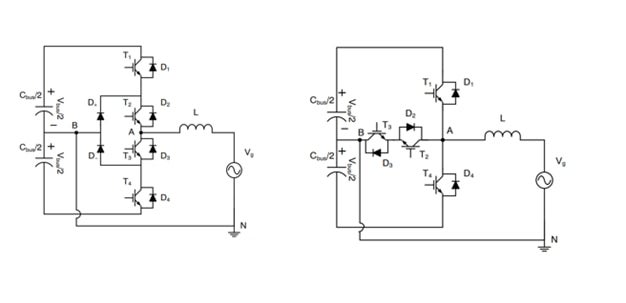
For applications like uninterruptible power supply (UPS) and solar inverters, new topologies with multi-voltage levels have been designed to overcome these limitations. The most common structures are the unipolar switching I−Type and T−Type converters which can operate off higher bus voltages. In addition, more output states reduce voltages across the filter, meaning smaller components can be used. These topologies are suitable for higher frequencies (16kHz ~ 40kHz) and offer excellent efficiency (~98%) due to lower switching losses.
Figure 6: I-Type and T-Type converter topologies
What does the future hold for IGBTs?
IGBTs have been around for quite a while and are still ideally suited for many high-voltage and current applications. However, their usage is not confined to classical designs – they are increasingly finding their way into newer ones. This is because more recent devices have novel structures that push Vcesat ever lower (towards 1V) with increased current density and lower switching losses. Maximizing the benefits of using IGBTs is about understanding the application requirements and choosing the correct circuit topology.
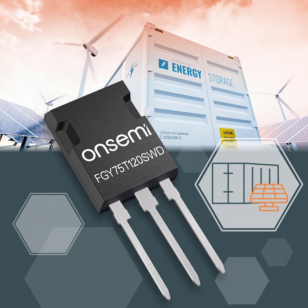
onsemi introduced 1200 V Trench Field Stop VII (FS7) IGBTs that minimize conduction and switching losses with industry-leading performance.
The new 1200 V devices offer the market's best conduction and switching performance. The FGY75T120SWD provides one of the best switching performances among 1200 V IGBTs currently available. The FGY100T120RWD shows a Vcesat as low as 1.45 V at the 100 A rated current, an improvement of 0.4 V over previous generation devices. Intended to enhance efficiency in fast switching applications, the new devices will be primarily used in energy infrastructure applications like solar inverters, uninterruptible power supplies (UPS), energy storage and EV charging power conversion. The new 1200 V Trench Field Stop VII (FS7) IGBTs are used to boost input to high voltage (Boost stage) as well as the inverter to provide an AC output in high switching frequency energy infrastructure applications. The low switching losses of FS7 devices enable higher switching frequencies that reduce the size of magnetic components, increasing power density and reducing system cost. For high-power energy infrastructure applications, the positive temperature coefficient of FS7 devices enables easy parallel operation.
Figure 7: 1200 V Trench Field Stop VII (FS7) IGBTs
Learn More about onsemi’s IGBTs as well as IGBT gate drivers.