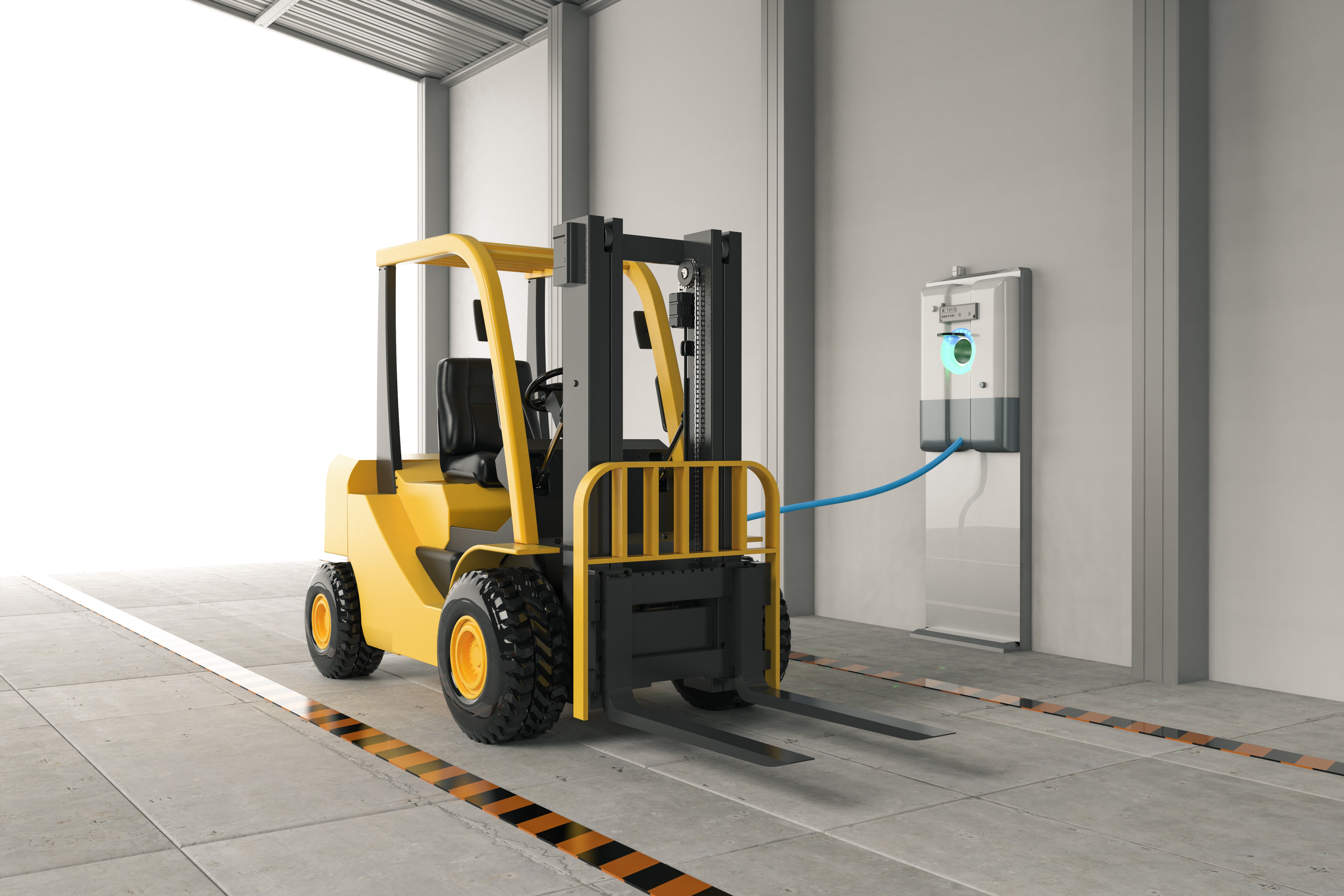
The world of industrial equipment is going electric, demanding robust, reliable, and efficient battery charging solutions. From power tools to heavy machinery, these chargers must handle harsh environments, diverse power sources (120-480 Vac), and prioritize compact size, light weight, and natural convection cooling. This blog series (Part1 and Part 2) serves as a guide for engineers designing these critical systems, focusing on topology selection and component choices, particularly the game-changing Silicon Carbide (SiC) MOSFETs.
The Modern Industrial Charging Landscape
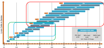
Industrial battery chargers face the challenge of supporting various battery chemistries. Lithium-ion batteries, especially in the 12V-120V range, have become the dominant choice for industrial applications (Figure 1), powering everything from handheld tools to material handling equipment.
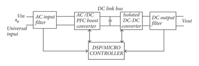
A typical industrial charger architecture consists of two key stages:
- Power Factor Correction (PFC): This front-end stage ensures efficient power utilization from the AC mains, minimizing harmonic distortion and maximizing power delivery.
- Isolated DC-DC Stage: This stage provides isolation for safety and regulates the output voltage and current to precisely charge the battery.
Microcontrollers often manage the charging process, adapting to different battery characteristics. High-frequency operation is crucial for fast charging and high efficiency. SiC MOSFETs are perfectly suited for this demanding environment. Their ability to operate at high frequencies with minimal switching losses allows for compact, passively cooled designs – a critical advantage in industrial settings.
Choosing the Right Topology: The PFC Stage
Power Factor Correction (PFC) stage is essential for efficient power conversion. Let's explore key topological options:
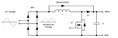
1. Boost PFC:
This widely used topology (Figure 3) employs an EMI filter, bridge rectifier, boost inductor, boost FET, and boost diode. Controllers like onsemi’s NCP1654/NCP1655 are commonly used to manage the power factor and minimize Total Harmonic Distortion (THD). For higher power levels, interleaved PFC using controllers like the FAN9672/FAN9673 is a better choice. For the boost diode, 650V EliteSiC diodes offer excellent performance. SiC MOSFETs are ideal for the switching element in high-frequency, high-power (2kW-6.6kW) applications. For lower power applications (600W-1kW), consider the NCP1681 totem pole PFC controller with integrated GaN drivers. At lower frequencies (20kHz-60kHz), Silicon superjunction MOSFETs or IGBTs can be used. A critical consideration at higher power levels is minimizing losses in the bridge rectifier. Active switches (Si or SiC MOSFETs) in semi-bridgeless or totem pole configurations are often employed to improve efficiency.
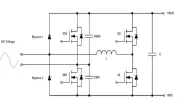
2. Totem Pole PFC:
The totem pole PFC topology (Figure 4) offers even higher efficiency by eliminating the traditional bridge rectifier. It includes an EMI filter, boost inductor, high and low-frequency half-bridges, gate drivers, and a dedicated totem pole PFC controller (e.g., NCP1681B).
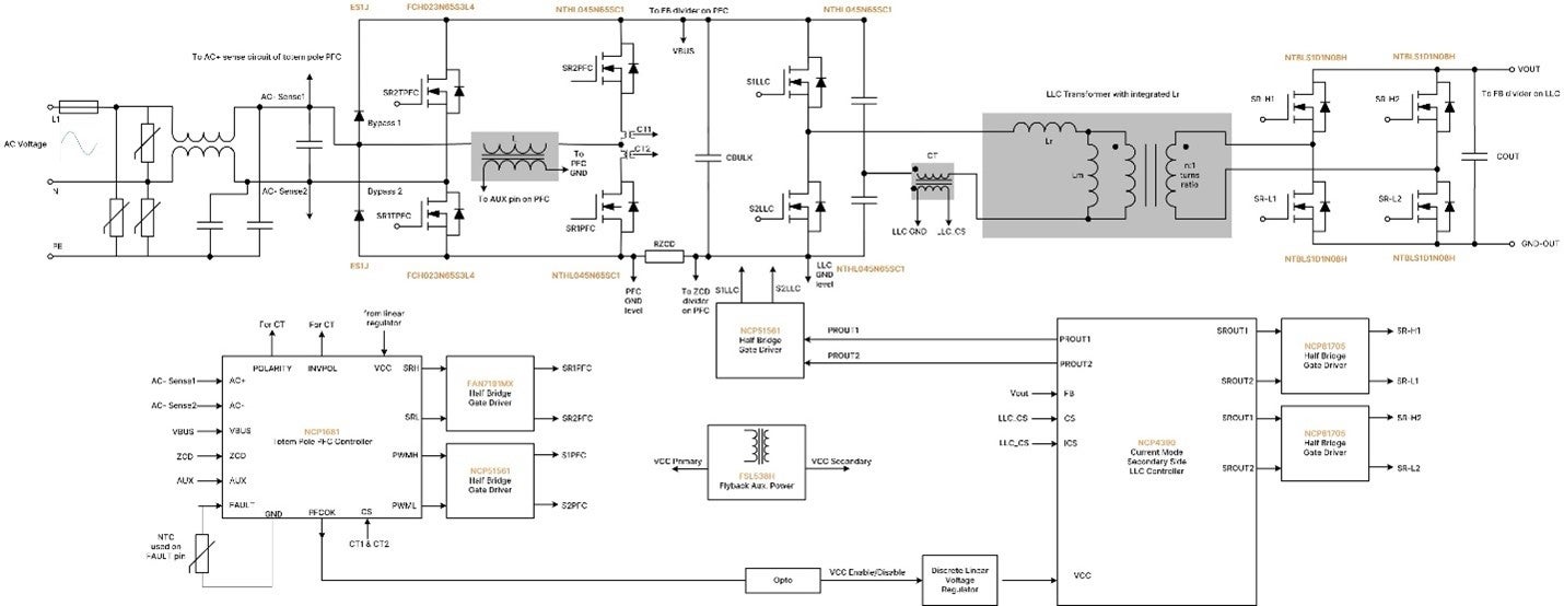
The high-frequency leg of the totem pole PFC requires a power switch with a low reverse recovery time, making SiC and GaN devices ideal. onsemi recommends integrated GaN drivers for applications from 600W to 1.2kW and SiC MOSFETs for 1.5kW to 6.6kW. IGBTs with integrated SiC diodes can be used at lower frequencies (20-40kHz). Low RDS(on) Silicon Superjunction MOSFETs or low VCE(SAT) IGBTs are suitable for the low-frequency leg. For higher power (4.0kW-6.6kW), consider an interleaved totem pole PFC configuration. onsemi’s 650V EliteSiC MOSFETs (like the NTH4L032N065M3S and the NTH4L023N065M3S for 3kW, and the NTH4L015N065SC1 or SiC Cascode JFETs such as the UJ4SC075009K4S for 6.6kW) are excellent choices for the high-frequency leg. The NTHL017N60S5H or SiC Combo JFETs such as UG4SC075005L8S suitable for the low-frequency leg. Figure 5 provides a practical example of a SiC-based 3kW totem pole PFC and LLC power supply. (An example of SiC-based 3 kW totem pole PFC and LLC power supply is shown in Figure 5.)
In part 2 of this blog series, we will explain details about isolated DC-DC stage and key topologies and component selection criteria.
Learn more about the 650V EliteSiC MOSFETs, SiC Cascode JFETs and SiC Combo JFETs.