Even the humble fuse cannot escape progress as the simple wire-in-a-glass-cartridge approach is giving way to intelligent electronic fuses (eFuses) that offer far more capability and sophistication.
Although a lot has changed, the fundamentals remain the same – all fuses are protection devices that protect circuits from overcurrent situations, whether that is hundreds of amps, or a few milliamps. Protection normally entails disconnecting the circuitry from the power source. With traditional fuses this means that the integral fuse wire melts, requiring physical replacement of the fuse. With an eFuse, disconnection is facilitated with a semiconductor switch which allows the device to be reset – often automatically.
Browse onsemi current protection devices: Current Protection
It is simply the wire in a conventional fuse that defines how it disconnects the load (a.k.a. “blows”) while eFuses are able to have this characteristic modified, most commonly through the application of an external resistor to a dedicated pin. However, to understand the way that eFuses “blow” requires considering much more than just the current passing through the device.
The first step is to understand the thermal characteristics of the eFuse as this can vary significantly. With the high currents involved, thermal stress is a common failure mode for many systems – and becoming more common as device geometries reduce.
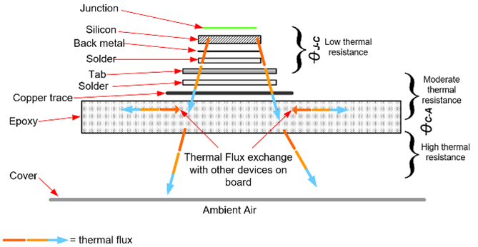
The thermal performance of any device (including eFuses) is linked to the physical size and construction. In most designs there are a number of layers between the semiconductor junction and the ambient air and it is this “thermal ladder” through which heat energy must pass to be dissipated.
Moving heat takes time, so the heat energy associated with short pulses will remain entirely within the device. In many eFuses (depending upon the thermal capacitance), some of the heat energy from pulses longer than 10 ms will reach the package and begin to dissipate into the ambient air or the PCB on which the device is mounted.
Analyzing the current at steady state will permit the RDS(ON) of the eFuse to be determined based upon the thermal impedance (ºC/W), ambient temperature and maximum junction temperature. From this, the designer will be able to calculate the limits of operation for a particular device.
Next, the dynamic performance is assessed by applying high current pulses of various durations. From this it is possible to deduce (and plot) the thermal impedance against pulse duration.
In general, the thermal impedance will be lower for shorter pulses and parameters such as RDS(ON) and die size will define the shape of the impedance curve for these shorter pulses. For longer pulses (where the heat energy has time to propagate through the device), the PCB will have a greater impact. Attributes such as more layers and heavier copper as well as features such as thermal pads will change the shape of the curve.
While the characterization method is consistent, it must be performed on an application-by-application basis to take account of the variable factors (such as the PCB). Only by doing this and having a clear understanding of the amplitude and duration of current pulses, can the correct eFuse be specified for a particular application.
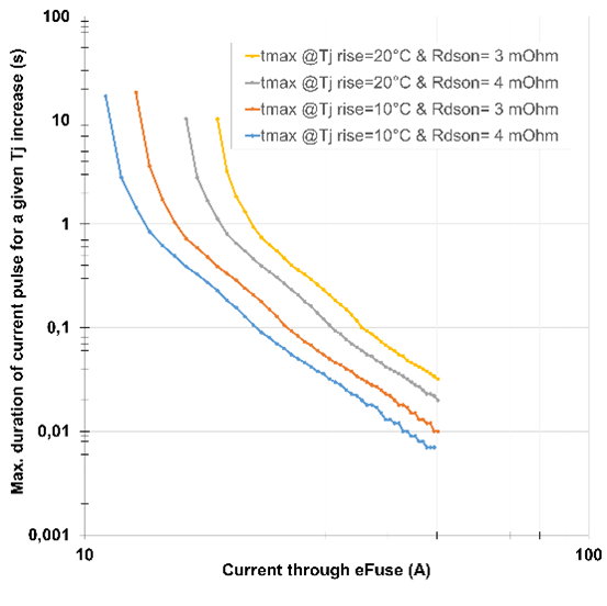
Although this characterization is useful, for practical usage the impedance vs. time curve needs to be inverted to give current vs. time. To do this, RDS(ON) and ∆t (acceptable change in die temperature) must be known.
From these curves, the maximum duration of a pulse for a given rise in junction temperature (Tj) can be quickly and easily determined. Of course, good design practice dictates that some safety margin should be allowed and this is determined on a case-by-case basis for each application.
The final consideration is to look at any wiring that carries current which will pass through the eFuse. The parameter use is “current squared x time” or I2t. For a traditional fuse this is usually defined as a constant value, along with the nominal fuse current.
However, this straight-line approach artificially limits the performance as a wiring harness is capable of longer durations when the current is lower. For this reason, in an eFuse trip points will normally follow a curve, allowing for more of the system capability to be used.
Taking this curve approach will allow system elements to be sized appropriately for the necessary performance and will save space, weight and cost.
Future eFuses
onsemi is now in the process of developing eFuses that can operate with a non-constant I2t where the curve points and parameters can be programmed (and if desired re-programmed) using a serial communication protocol such as I2C or SPI. Included within the fuses will be a number of typical curves that can be user-selected as a starting point for new designs.